Speedometer correction.
There's been some interest in another thread in speedometer correction for use with larger tires, and maybe different gear sets, so I'm putting this in it's own thread.
http://www.jaycar.com.au/productView.asp?ID=KC5435
Jaycar in Australia offer a digital speedometer corrector - please note I have not used this personally, but I know of folks who have used it successfully on other makes of 4WD, and see no reason why it should not work on an iO - the speedometer on the iO is not the old school cable driven speedometer, but is electrically operated and gets a signal from a sensor in the transfer case, the Jaycar corrector can be fitted in between the sensor & the speedometer to provide a correction.
The corrector is a 4 wire device - requiring ground, a +12V supply from the vehicle's igntion system an input from the speed sensor and an output to the speedometer - all of these connections can be made in the area behind the instrument cluster. The cluster has three connectors, 1 x 12 way and 2 x 14 way, we're interested in the two 14 way ones, it shouldn't be two difficult to figure out which is which from the wire colors - tap into the ground & power wires, the blue/white I/O signal wire needs to be cut, and the corrector connected "in-line".
Ground - Connector C-05, pin 34, wire color - black
+12V Switched - Connector C-06, pin 1, wire color - black/white
I/O signal - Connector C-05, pin 23, wire color - white/blue
Claude - can I ask a favour ...
What did it cost and can you find out what it would cost to mail one to me (Guyana, South America) using parcel post.
I don't need one right now, but I am contemplating a change in tire size on my GV and if I go that route, I would need one then.

speedometer correction
No problem...The total cost was just under $70 delivered to my house. I bought an extra small plastic box to enclose the kit properly ($4) and $2 surcharge for credit card payment. I will enquiry about the cost of postage to your place.
I am going to do the soldering this week end, I might need some extra advice to find the plugs to connect it....
I will PM you early next week for the freight, total cost. But it shouldn't be too bad, it is very light.
I will send Jaycar an email to see if they could send one to you directly.
Happy io
Thanks a million Claude
I don't know why I didn't think of asking Jaycar if they would ship outside of Australia, I guess I've gotten accustomed to US firms who are reluctant to get involved with international shipping - most of what I buy in the US either comes with me in a suitcase, or gets dropped off at a freight forwarder in Miami.
jaycar speedo corrector build up
Like you,... always a pleasure to help....I have send an email to Jaycar to ask them if they could post directly to you....if not, or no reply, I will get you one. Let me know how you go on your side (if you contact them)
I have finished to build the kit....if you are not too good with your soldering, ask some help, as some are very close to each other....
I am not sure when I will try to connect it, I have to search for the plug...I will probably have to remove the speedo...
Some pictures....
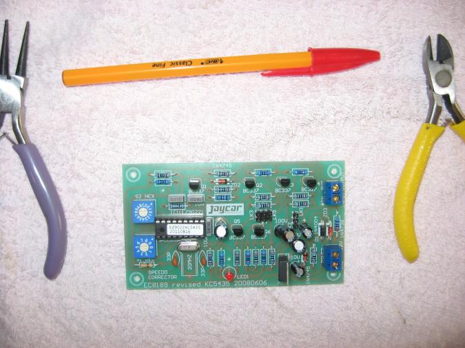
Before the build

Finished
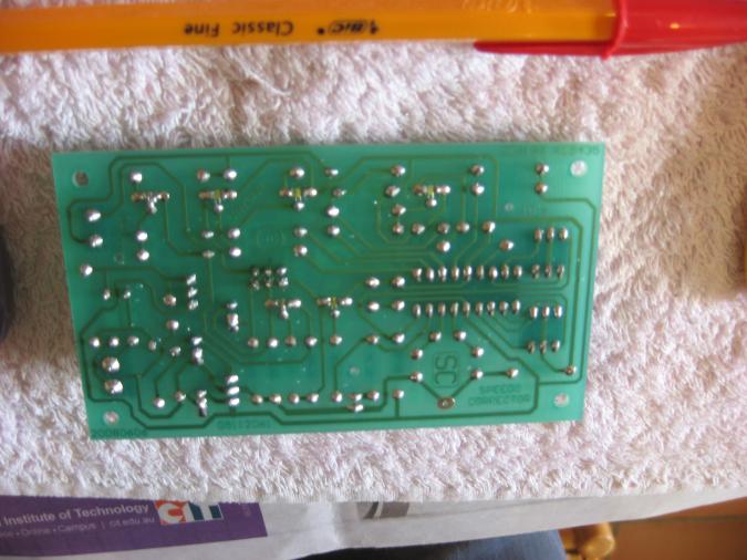
The back of it, you can see some of the soldering that are very closed to each other
More to come later on...
Happy io

speedo corrector
I think that it is only available online. Mine is now working, I have one problem: it does have a led to let you know that the kit received the speedo input, and when you change the setting from lowering or increasing the speedo. My led is not working, but I can do everything else.....
If you get the kit, you might be able to help. They have 5 links, first time connected, you to have to connect the link 2, go for a drive, if the led is not flashing then try to connect link 1. Then I am a bit confused on the next step, (led still not flashing), I connected link 3 (no other) and it does work but no flash from the led. On the net I found some people have connected link 1 or 2, and then (with link 1 or 2 connected) link 3 or 4 or 5.
http://www.offroad80s.com/jaycar-speedo-corrector-build-and-installation-t482-15.html
http://performanceforums.com/forums/showthread.php?67254089-Jaycar-Coach-speedo-corrector-input
http://www.trueblueford.com/discussion_new/viewtopic.php?t=3187
I have another go later today...
Happy io
LEDs are polarity sensitive
Did you put it in the right way around? There's usually a little flat spot on the base to indicate which way is which.
Edit...
You say the LED is not working but you can do everything else - the LED is driven from the output of the device, so as long as you're getting a reading on the speedometer, it means the device is sensing input, so I suggest you go ahead & calibrate.

Fordem might be right
Just a quick look at the pics posted (zooming in a bit), it does look like the flat (-) side of the LED is facing up, but the screen printing on the board itself has the flat at the bottom.
Not a bad effort to get the kit working first go though (almost).. Was it hard to install under the dash?
led
I will try to change the polarity...tomorrow, maybe put a new one ?? All the parts that have a polarity is showed on the circuit with a clear "+" but not for the led. They showed the polarity on the instruction but not on the board itself....
I have tested everything else, and while the led is not flashing, all is working.....you can lower or increase the speedo reading by 1 to 99%, I changed it from increasing to lowering...all good...but the led. (it could have been a lot worse!) I will do the final connection later with a couple of pictures to show the cable.
Fordem, thanks for your cable description, while I wasn't sure about the pin number you mentioned, the white and blue was there and it is the speedo, the other were confirmed with a voltmeter. It saved me a lots of time....and 2 extra grey hair :)
As an advice for anyone wanted to buy this kit ,buy the advised plastic box to go with the kit, nice and tidy and only $4 extra.
Happy io
The polarity IS shown
It's not so much that they don't show the polarity, but that the "flat" on the LED that indicates which lead is which, is not very easy to see, especially on those smaller LEDs - those of us who work with them have learned what to look for. When LEDs were first introduced in the late 70's, they were about four times that size, and the flat was hard to see then, now it's - well - even harder.
Update
http://search.jaycar.com.au/search?w=speedo%20corrector&view=list
Apparently Jaycar no longer offer this product as a DIY kit, but as a fully assembled & tested product at a lower price - the pictures in the manual appear different to those Claude has posted, but the installation & calibration instructions are similar.
For those of us outside of Australia & New Zealand, Jaycar has also opened webstores specifically targetting the UK, US & Canada.
Jaycar digital speedometer corrector
I ordered and just received one of these....hum...it is really a kit, that you have to built !, you have to solder all the parts yourself. The instruction is a bit technical (to me anyway) and not very clear..ie: I still cannot find "fig 1" . Anyway, I will give it a go....
Happy io
My io is now SOLD Thankshttp://pajerio.com/forum/claudes-io-2002-zr-built-thread-onlyhappy-io